Inside an industrial PC, on the workbench, or connected to a battery pack. Choose by where the interface will live and what it needs to connect.
1
1 DualCANFD · Mini PCIe module inside the host
INTERNAL CAN FD
Two CAN networks. Inside the PC.
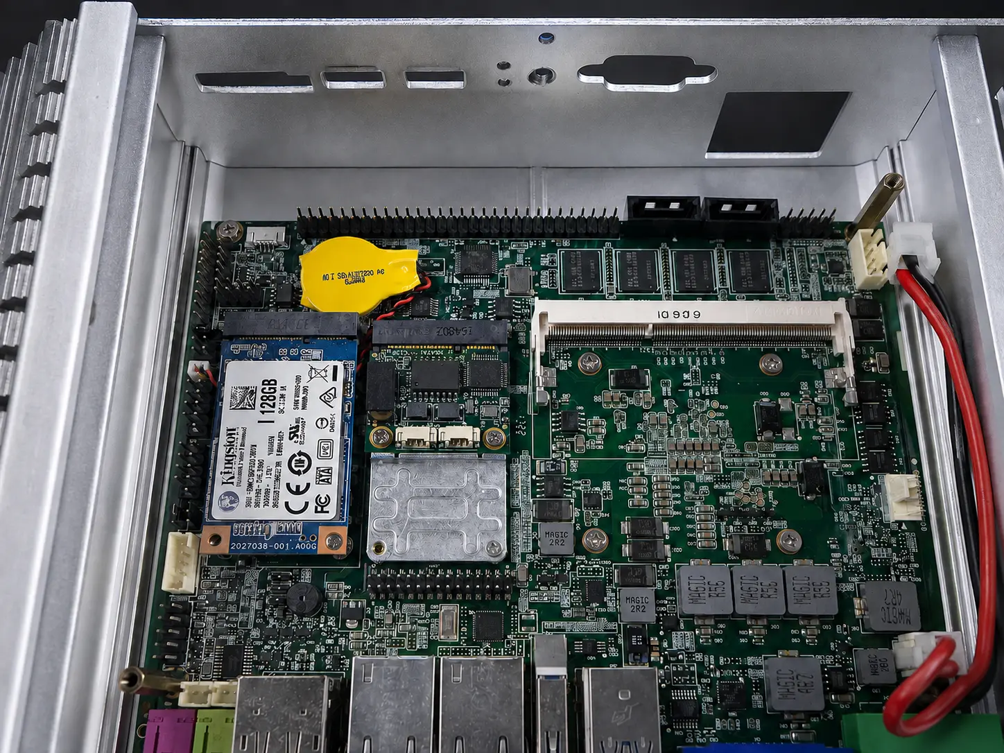
DualCANFD occupies a compatible Mini PCIe slot, keeping the interface board and host connection inside the chassis. The example shows the module beside the computer’s storage device.
Host connection
Mini PCIe slot with USB 2.0 signals
Added interfaces
2 independent CAN / CAN FD channels with signal isolation
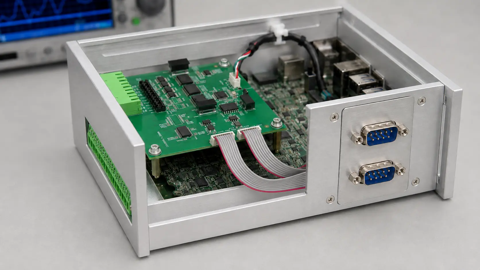
XE826 mounts on standoffs inside the enclosure and connects to an internal USB header. In this installation, ribbon cables bring the CAN connections to two panel DB9 connectors, while the serial terminals remain accessible through the chassis.
Installation examples show interface placement and connector routing. Host computers, panel assemblies, and cables are shown for context; confirm the required hardware and accessories for your installation.
BEYOND THE CHASSIS
Interfaces for the rest of the system.
WORKBENCH & FIELD
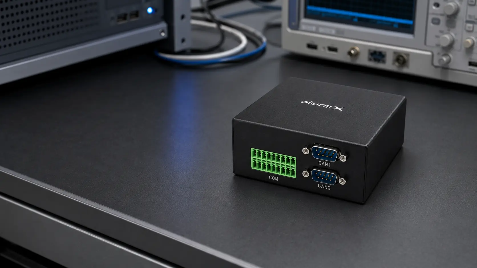
Octant
Connect a Windows or Linux computer to two CAN FD, four RS-485, and two RS-232 channels through external USB. An enclosed format for equipment evaluation, communication capture, and test setups.
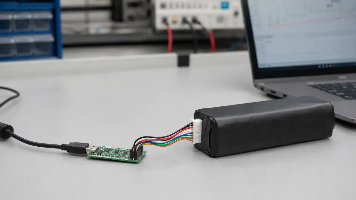
Bring supported pack-reported battery information to Windows and Linux. Check the battery gauge, communication protocol, and host requirements before choosing the interface configuration.
XL interface ICs provide a board-level integration path. Compare channel combinations, then review the device documentation for the required peripheral circuits.